

Is anyone still interested in break out boards for the Solo?
I got my Solo in October, started looking at the Accessory bay for a project, and the only break out boards I found were somewhat lacking (IMHO).
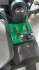
So, I made my own. See attached pix. Yes, it DOES clear the gimble.
Pro's:
No expensive hard to find ClickMate connectors.
All pins broken out, so if 3DR decides to use those extra pins for something some day, it's ready.
Adjustable switching step-down regulator from raw Batt voltage.
3.3V linear regulator.
USB connected directly to Accessory Bay connector, better USB signal integrity (equal length D+ and D-, no stubs).
Isolated UGND plane.
Holes for mounting to the Solo Body.
Hole for Pairing switch.
Additional boards can be stacked using the pins at P1 & P2 arduino style.
Nice Green soldermask.
Con's:
No fuse or other protection methods. BE CAREFULL!!! (Yep, I should have put one in...)
No ClickMate connectors.
No Arduino UNO/Nano/Teensy position.
No fancy board outline, but it does clear the Gimble.
No additional mounting holes for stacking boards.
Step down regulator position takes up lots of space.
>>>3.3V linear regulator shape had wrong pinnout, all boards reworked, but copper area isn't perfect for regulator, so limit 3.3V load.<<<
Additional notes:
Be careful of the Solo's +5Volts. The Solo Dev Guide says it is 5.35V, which is .1V over the max spec for USB.
When I measured it it was 5.41V, which is .06V above 5.35V. Does this matter? Well, it might, depending on what you connect it to.
I asked about this on the dev forum and never received a response. YMMV.
In addition, the 5V is not switched, so when the iMX6 is in OTG mode the 5V is still there which may effect you if you plug it into a PC.
Why an step down module and not just put on all the parts? Well, you can buy these LM2596 modules on e-bay for less than the parts cost,
and this is just a prototype board not really meant to fly around too much.
I made 10 of these PCB's and have populated and have tested one. I'll keep a couple for myself and will put the remainder up for sale if there is any interest.
>>> I have the proper JAE and USB connectors as well <<< as they are somewhat hard to find.
If there is enough interest, I could make more, or do something different, or just climb back in my cave.
Let me know whether there is any interest, or not.....
Price for board + JAE + USB (not soldered) would be $15 + shipping, within US only.
...ken...
I got my Solo in October, started looking at the Accessory bay for a project, and the only break out boards I found were somewhat lacking (IMHO).
So, I made my own. See attached pix. Yes, it DOES clear the gimble.
Pro's:
No expensive hard to find ClickMate connectors.
All pins broken out, so if 3DR decides to use those extra pins for something some day, it's ready.
Adjustable switching step-down regulator from raw Batt voltage.
3.3V linear regulator.
USB connected directly to Accessory Bay connector, better USB signal integrity (equal length D+ and D-, no stubs).
Isolated UGND plane.
Holes for mounting to the Solo Body.
Hole for Pairing switch.
Additional boards can be stacked using the pins at P1 & P2 arduino style.
Nice Green soldermask.
Con's:
No fuse or other protection methods. BE CAREFULL!!! (Yep, I should have put one in...)
No ClickMate connectors.
No Arduino UNO/Nano/Teensy position.
No fancy board outline, but it does clear the Gimble.
No additional mounting holes for stacking boards.
Step down regulator position takes up lots of space.
>>>3.3V linear regulator shape had wrong pinnout, all boards reworked, but copper area isn't perfect for regulator, so limit 3.3V load.<<<
Additional notes:
Be careful of the Solo's +5Volts. The Solo Dev Guide says it is 5.35V, which is .1V over the max spec for USB.
When I measured it it was 5.41V, which is .06V above 5.35V. Does this matter? Well, it might, depending on what you connect it to.
I asked about this on the dev forum and never received a response. YMMV.
In addition, the 5V is not switched, so when the iMX6 is in OTG mode the 5V is still there which may effect you if you plug it into a PC.
Why an step down module and not just put on all the parts? Well, you can buy these LM2596 modules on e-bay for less than the parts cost,
and this is just a prototype board not really meant to fly around too much.
I made 10 of these PCB's and have populated and have tested one. I'll keep a couple for myself and will put the remainder up for sale if there is any interest.
>>> I have the proper JAE and USB connectors as well <<< as they are somewhat hard to find.
If there is enough interest, I could make more, or do something different, or just climb back in my cave.
Let me know whether there is any interest, or not.....
Price for board + JAE + USB (not soldered) would be $15 + shipping, within US only.
...ken...